
Answer Preview: Project 3: Local Area Networking – Enabling VLANs & Trunks
In this assignment, you will install and configure two Layer 2 switches, enable VLANs for increased security, and interswitch trunks for (redundancy/resiliency). You will add PCs to each VLAN to test and demonstrate connectivity.
You will use troubleshooting commands to identify informational items to aid in the troubleshooting process.
Unless otherwise directed:
• Use the CLI (Command Line Interface) to complete networking device configurations.
• Use the ‘IP Configuration’ tab to configure the PC networking interfaces.
• Use the ‘Command prompt’ to execute troubleshooting commands.
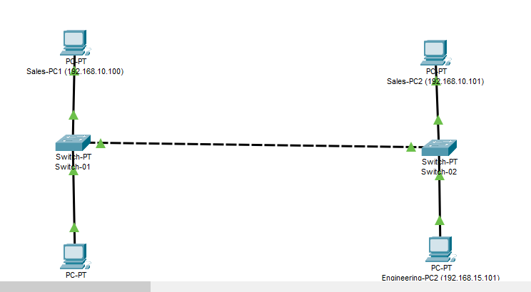
Figure 1 Example Completed Project
Project 3 – Instructions:
Open Packet Tracer.
Open a new tracer file (or work with a new blank workspace).
Locate ‘Switches.’
Add a new Switch-PT switch to the workspace (see Appendix A: Sample devices)
1. Locate the ‘Physical’ Tab.
2. Power Off the switch.
3. Remove the following interface modules:
a. NM-1FGE in Slots 5 & 6
b. NM-1CGE in Slot 4
4. Add the following interface modules:
a. NM-1CGE in Slot 9
5. Power On the new switch.
6. Right-Click on the switch.
7. Select the ‘Config’ tab.
Page 3 of 33
Figure 2 – ‘Config’ tab
8. From the Config Tab:
a. Set the Display Name to Switch-01.
b. Leave the hostname at default.
9. Select the CLI tab.
Figure 3 – CLI Window
10. Expand CLI to full screen.
11. Press RETURN to begin!
12. Enter Privilege mode. (Hint: enable)
13. Enter Global Configuration mode. (Hint: conf t)
Description: Initial Setup
The following configuration items are typically performed once on initial setup.
Standard settings:
Page 4 of 33
1. Configure a hostname
hostname Switch-01
2. Disable IP domain-lookup
no ip domain-lookup
The following configuration items are used to configure VLANs
3. Create new VLANs and set descriptions:
vlan 10
name SalesFloor
vlan 15
name Engineering
vlan 99
name NetManage
Figure 4 Command Examples
The following configuration items are used to configure port types and VLAN assignments.
Enter interface configuration mode.
4. Select an interface to set to access mode.
Interface fastEthernet0/1
5. Configure the interface as an access port.
Switchport mode access
6. Assign the interface to a VLAN.
Switchport access vlan 10
7. End interface configuration mode.
End
Page 5 of 33
8. Display VLAN configuration.
show vlan
Figure 5 ‘show vlan’ result
9. Repeat steps 4 through 8 for FastEthernet 1/1, placing it in VLAN 15.
10. Confirm that your selected interfaces are part of the correct VLANs.
(Repeat the show VLAN command.)
11. Configure a trunk interface.
12. Enter interface configuration mode for Gigabit9/1.
a. Switch-01#configure terminal
b. Switch-01 (config)#interface Gigabit9/1
c. Switch-01 (config-if)#
13. Set interface mode to trunk.
a. Switchport mode trunk
14. Set trunk to allow desired VLANs.
a. Switchport trunk allowed vlan 10
-Orb. Switchport trunk allowed vlan 10-99
-Orc. Switchport trunk allowed vlan 10
d. Switchport trunk allowed vlan add 15
e. Switchport trunk allowed vlan add 99
Adding a second switch demonstrates expanding network capacity while retaining VLAN (broadcast domain) efficiencies.
Page 6 of 33
15. Add a second SWITCH-PT device.
a. Power off, remove the NM-1FGE modules.
b. Add NM-1CGE in Slot 9.
16. Repeat the administrative and interface configuration steps from the previous section for the second switch.
a. Use Switch-02 as the hostname and display name.
b. Create the same VLANs, assign the same ports, VLANs, and trunks.
17. Continue here once Switch-02 is ready.
Use the connector tool to connect Switch-01 to Switch-02.
18. Use a Cross-Over ethernet cable to connect Gigabit 9/1 on Switch-01 to Gigabit 9/1 on
Switch-02.
Figure 6 Cross-over cable
Add two PC devices to each switch to demonstrate network connectivity.
Locate ‘Devices.’
For Switch-01:
19. Add one PC to the drawing.
a. Locate ‘Config’.
b. Set display name to ‘Sales-PC1 (192.168.10.100)’.
Figure 7 PC Device Label
20. Configure its IP address: (see Figure 8 below)
Page 7 of 33
a. Locate ‘Desktop’.
b. Locate ‘IP Configuration’.
c. Set the IP address to ‘192.168.10.100’ .
d. Leave subnet mask as default (255.255.255.0).
e. Set the default gateway to 192.168.10.1
f. Do not set a DNS.
Figure 8 Desktop > IP Configuration
21. Connect this PC from its ethernet port to FastEthernet0/1 on Switch-01.
22. Add another PC to the drawing (near Switch-01):
a. Set the display name to ‘Engineering-PC1 (192.168.15.100)’.
b. Set the IP address to ‘192.168.15.100’.
c. Leave the subnet mask as default (255.255.255.0).
d. Configure a default gateway (192.168.15.1).
23. Using the connector tool, connect this PC from its ethernet port to the Switch-01 port in VLAN 15.
24. Repeat each step for Switch-02, with the following changes:
Assign 192.168.10.101 to the PC in VLAN 10, Label it ‘Sales-PC2 (192.168.10.101)’.
Assign 192.168.15.101 to the PC in VLAN 15, Label it ‘Engineering-PC2 (192.168.15.101)’.
a. Set the gateways on both devices to be consistent with other devices in the same VLAN.
Description: Test your network.
Using commands learned in the OSI troubleshooting topic, verify configuration information and test network
connectivity. You may need to review Topic 2 (network configuration). You may also need to verify and correct some of
your configuration steps in this activity.
Page 8 of 33
Confirm your work:
Investigate following scenarios:
1. Using the command prompt and the appropriate windows command, confirm that each device is properly
configured with an IP address, Subnet Mask, and Default gateway.
a. Are you able to identify the interface configuration items?
i. If not – review your device configurations and correct as needed.
2. Using the command prompt and the appropriate windows command, test connectivity between each device
in the same VLAN.
Can the PC in VLAN 10 on Switch-02 ping the PC in VLAN 10 on Switch-01?
a. If not, why not?
i. Review your switch configurations.
ii. Follow your troubleshooting approaches from Unit 1 to determine the issue.
Repeat this test for the PCs in VLAN 15.
3. Using the command prompt and the appropriate windows command, test connectivity between each device
in different VLAN.
Repeat this test for a PC in VLAN 10 to a PC in VLAN 15.
i. Does this work?
ii. Why or why not?
Project 3 – Scoring (30 points total):
Configure Switches with correct interface modules: 10 points
Configure VLANs with correct VLAN designation: 5 points
Configure Trunks for VLANs, connect cable: 5 points
Configure IP settings on PCs: 5 points
Network functions properly: 5 points
Project 3 – Complete and submit your work
SAVE your Packet Tracer file as follows:
finitial-lname-section-project-3 i.e., fflintstone-itt116TR100A-project-3
ZIP the file – keep the name intact. i.e., fflintstone-itt116TR100A-project-3.zip
SUBMIT the completed packet tracer file as a ZIPPED file to the assignment page in the digital classroom.
Screenshots are not acceptable.